Connections to the microscope are made through connectors on the front of the NanoScope V Controller. The table below provides descriptions of the main front panel connectors:
| Connector Label | Connector Type | Purpose |
|---|---|---|
| High Voltage/Digital | 36-pin combo D-sub, female | Piezo drive/digital control between controller and E-box/SPM |
| Low Voltage | 78-pin B, male | Differential low voltage analog/digital (LVDS) signals between controller and E-box/SPM |
| Angler | 25-pin DB, female | Communicates with PicoAngler |
| Computer (back panel) | 68-pin micro-SCSI, female | Data/control beween NS V controller and computer |
| Expansion (back panel) | USB type B | Data/control between NS V-PI controller and computer |
| Closed-loop Scanner | 14-pin Lemo, female | Input/output to the XYZ closed-loop scanner |
| Digital I/O | BNC, female | TTL-compatible synchronization signals (i.e., EOL and EOF) |
| High Frequency Analog | BNC, female |
Used as either a lock-in input or for HSDC Sample rate is 50 MS/s |
| Low Frequency Analog | BNC, female | Used for external measurement. Can bring up as a data type in NanoScope software. |
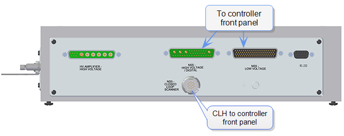
Figure 1: Microscope Electronics Box - rear view
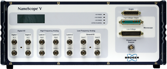
Figure 2: NanoScope V Controller - Front View
| www.bruker.com | Bruker Corporation |
| www.brukerafmprobes.com | 112 Robin Hill Rd. |
| nanoscaleworld.bruker-axs.com/nanoscaleworld/ | Santa Barbara, CA 93117 |
| Customer Support: (800) 873-9750 | |
| Copyright 2010, 2011. All Rights Reserved. |